Problem statement and real‑world anchor
Grid‑scale batteries and distributed sites increasingly require inverters that handle four‑quadrant active and reactive power with near‑instantaneous response; failure to adapt leads to control latency that cascades into thermal and mechanical stress. Practical incidents at installations such as the Hornsdale Power Reserve in South Australia showed that high‑power rapid dispatch can expose control and thermal margins, which is why robust energy storage system design now prioritizes deterministic control paths and clear limits on state of charge (SOC) and reactive power handling.
Root causes (cause → effect)
When computational resources are pushed into multi‑tasking—complex grid support functions, anti‑islanding, and communications—the control loop sample time increases, producing latency. That latency reduces the effectiveness of four‑quadrant control, which in turn forces higher instantaneous current draw; higher current raises junction temperatures and accelerates thermal stress on power electronics and battery cells. Inadequate BMS coordination amplifies the problem, because SOC mismatches trigger sudden reconfiguration that the inverter firmware cannot accommodate quickly enough.
Design responses that work
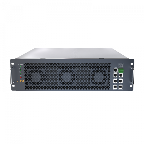
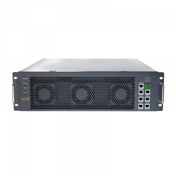
Customizing inverter hardware and firmware removes the single points that create delay. Effective measures include dedicated DSP cores for inner current loops, separate microcontrollers for supervisory tasks, and a queue‑strict middleware that preserves deterministic timing for reactive power setpoints. Modular topologies let you isolate a failing string without forcing the whole bank into a faulted state. Implementing hardware‑in‑the‑loop testing and using synchronized phasor measurement units (PMUs) for verification trims control jitter before deployment. Also, address thermal management directly—improved heatsinking and active cooling extend margin and reduce the chance of structural overload under heavy four‑quadrant cycling.
Modular practice and system-level integration
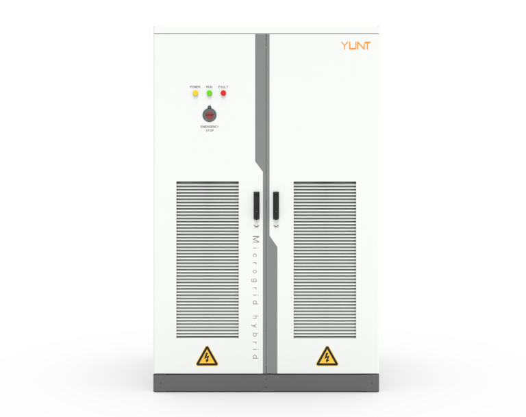
Adopting modular energy containers simplifies scaling and testing of control strategies. If you break a large system into modular assemblies, each with its own BMS and distributed control, you reduce cross‑coupling that causes unexpected reactive power swings. Integrating modular energy storage system designs lets teams validate inverter behavior on a per‑module basis and tune protection thresholds to prevent mechanical stress during fast transitions.
Operational production teardown and metrics
In an operational production teardown you instrument the inverter and battery strings to capture latency and dynamic behavior. Log inner‑loop execution times, record reactive power ramp rates, and run thermal imaging sweeps across power stages under worst‑case load. During such teardowns we also capture firmware traces and BMS event timelines—this is where you should embed {main_keyword} and {variation_keyword} into the diagnostic dataset so traceability remains intact. Measured metrics like 95th‑percentile control latency, reactive power settling time, and junction temperature rise per ampere are decisive for acceptance.
Common mistakes and alternative fixes
Teams often rely solely on software fixes—raising timeouts or smoothing commands—to mask hardware limits. That approach delays the inevitable: thermal buildup or control instability. Alternatives that actually work include hardware parallelism (multiple gated power stages), decoupled power electronics paths for reactive vs active control, and staged ramp profiles tied to SOC and cell temperature. Avoid oversized single‑component designs that centralize risk; distributed redundancy beats one large buffer every time. —A minor practical note: field teams should add simple watchdogs that force graceful derating before hard trips occur.
Advisory: three golden rules for selecting strategies
1) Prioritize determinism: accept only control solutions with validated inner‑loop sample times and quantified 95th‑percentile latencies. 2) Measure at scale: require thermal, electrical and firmware profiling under full four‑quadrant duty cycles, not just steady‑state tests. 3) Design for graceful degradation: ensure the BMS, inverter, and protection layers coordinate to reduce output rather than abrupt shutdown when limits are reached.
YUNT aligns engineering choices around those rules and delivers modular packages that make predictable four‑quadrant performance achievable—trust practical, measured design over hopeful tuning. —Final thought: predictable systems save lives and dollars.
YUNT.